Senior Engineering Taken to the Trails: Home Built Hardtail
After completing my third year of college, I was ready to step away from the textbooks to experiment with something more hands-on. Having spent the first half of my childhood living in Santa Cruz, mountain biking was always a big part of our community and I thought about building my own frame for years. I learned countless skills during the process and it made a huge contribution to my education. This isn’t a step by step guide, but more of a summary of my experience and lessons that I learned along the way.
Working in academia can be difficult. After multiple proposals and applications by the spring of 2019, I had obtained the University’s backing to complete the frame as part of an Independent Study course. I was granted access to a lab’s equipment and worked with Craig Severson, the lab coordinator and now good friend, who was always a great source of help and knowledge.
Design
I designed the frame using SolidWorks CAD software which was available to me on campus. This allowed me to play around with geometry, but also map out necessary bends and copes in the frame’s tubing. Using CAD software is completely optional, however, it does speed up the process which I will explain later. For those who are interested in software to use specifically for bike frames, I would look at Bikecad. If you are a student, free or reduced licenses for other CAD programs such as Inventor are available and while these programs are much more powerful, they will have a steeper learning curve.
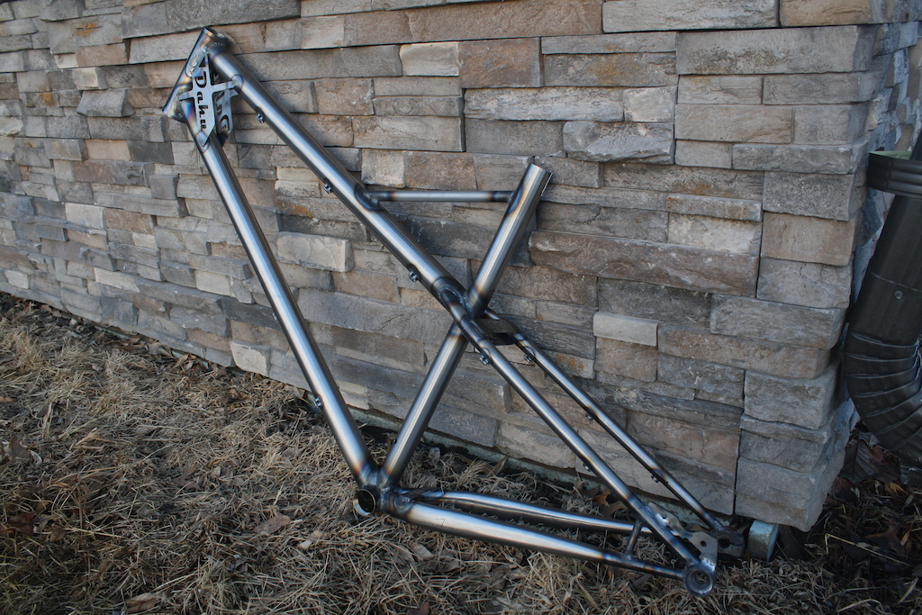
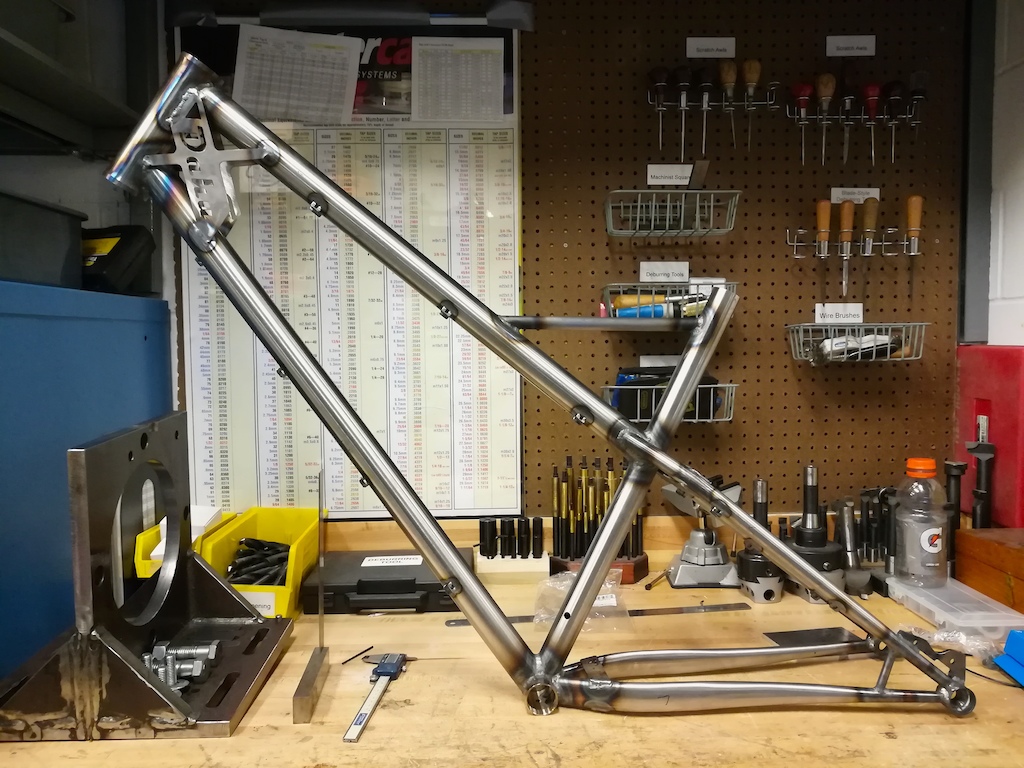
I wanted to build something a little out of the ordinary so I decided to design a 160mm hardtail with good high-speed stability, relatively long rear stays, a V-shaped frame to allow plenty of rider movement, and 27.5 plus capability (although it is currently not set up with plus tires).
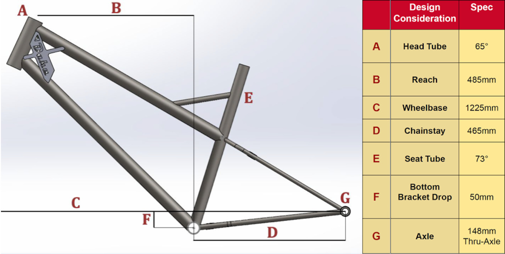
To create a smooth design, the top tube flows directly into the seat stays without any change in angle. Also, notice the parallelism between the chainstays, seat tube brace, and gusset brace.
To some people, the gusset brace seems unnecessary and on an XC build, I might also be convinced that was the case. However, with the slack head tube angles we are seeing today, welds experience significantly more stress during loading, therefore I deemed it necessary. The slacker the head tube angle, the larger the lever arm.

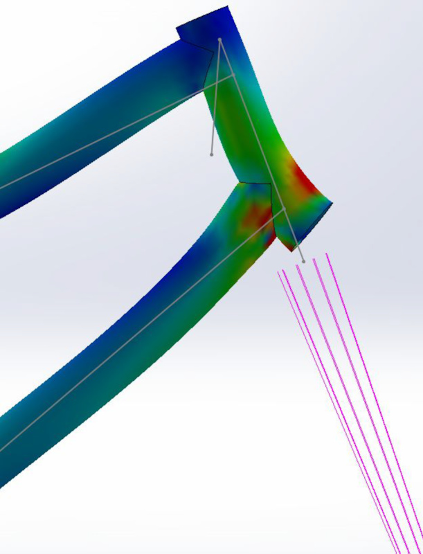
This is a stress plot diagram that I simulated comparing a more "traditional" geometry to today's slack angles. The remote load location was specified at the hub of the wheel, which is where the forces effectively act in this simplified example.
Materials
Since this was my first frame, I wanted to use the most forgiving material I could find. I settled with Nova 4130 single butted tubing from Cycle Frames. With a wall thickness of 0.9 mm at the thickest point, there was quite a learning curve when it came to welding. Although not renowned like Reynolds or Columbus, I have been thrilled with the performance per dollar factor achieved with Nova. A full break down of materials is included at the bottom of the article.
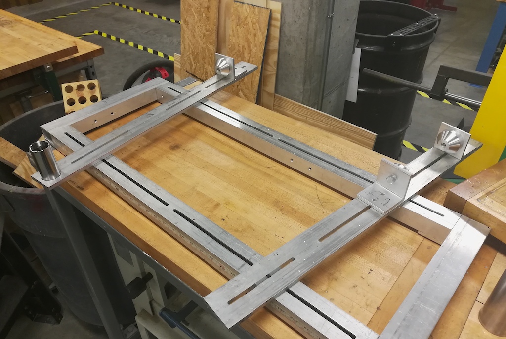
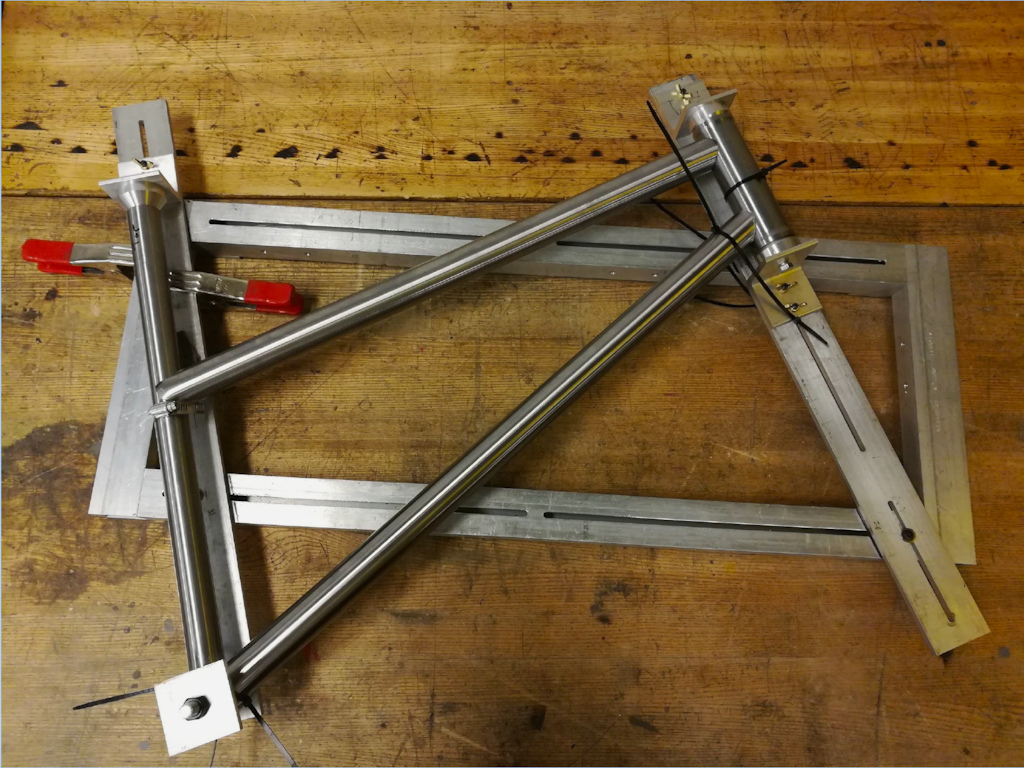
For the frame jig, I decided to use whatever was available to me. In the end, I decided to build two separate jigs. One jig for the main triangle, and one for the rear triangle. It worked out great and required a less complex setup. The main triangle jig was built using square extruded aluminum tubing, with 3/8” Aluminum plate. The rear triangle jig was made using T-slot aluminum extrusions.
Build - Part 1: Jigs
I built a rectangular frame with a track system in which the flat bars can maneuver. In order to secure them in place, I built a T-slot system that fits inside the jig before it’s assembled. The position of the entire main triangle is determined by using the bottom bracket as the starting point. A ring shape was machined into the flat bar, and the bottom bracket center height was measured. The height off of the plate was then used to drive the position of all other contact points. Then to hold the Seat Tube and Head Tube, steel cones needed to be turned on the lathe and attached with 90-degree extrusions.
The most important thing during jig construction was to allow for enough room to tack the frame on both sides while it was still secure. This ensured that when the welds cooled, the frame did not twist to either side. Although my jig wasn’t necessarily perfect (should have made it longer but ran out of material), it did the job for me and was a great budget saver.

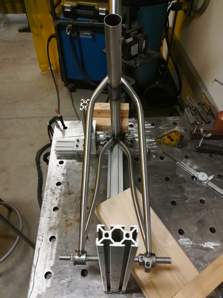
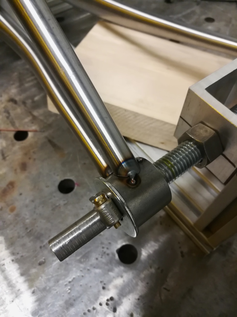
For the rear triangle jig, T-slot extrusions proved to be the best option. Securing the bottom bracket using the same steel cones meant I only needed a way to support the dropouts. A threaded rod with nuts that fit inside the dropouts allowed me to lock them in the correct position for welding.


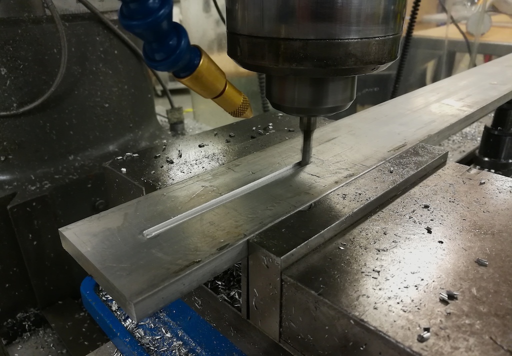
Build - Part 2: Coping Tubes
Coping, Notching, or Mitering the tubes is the process of cutting tubing into the correct shape so that it fits perfectly around the intersecting tube for welding.
This part is where having CAD software really saved me time. Using SolidWorks, I was able to model my entire frame as sheet metal. Individual components like the top tube could then be isolated, and “unfolded” within the program. Once printed at 1-to-1 scale, they were cut out and wrapped around the tubing. It created a perfect template to follow for coping the tubes and trimming lengths. Unfortunately I don’t have any pictures of this, but overall it worked great.
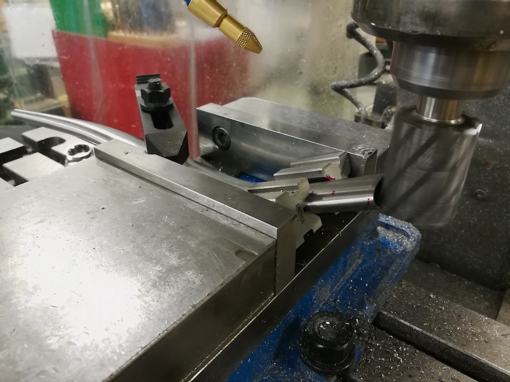
I used a mill to cope my tubes during this project, but it is completely possible to do it by hand. If filing tubes by hand, the risk for error is much lower since its a slower process and requires minimal experience and machinery. Taking my time through this step was critical, since the fit of the tubes would determine how easy the would be to weld as well as the strength of the frame.

Build - Part 3: Bending
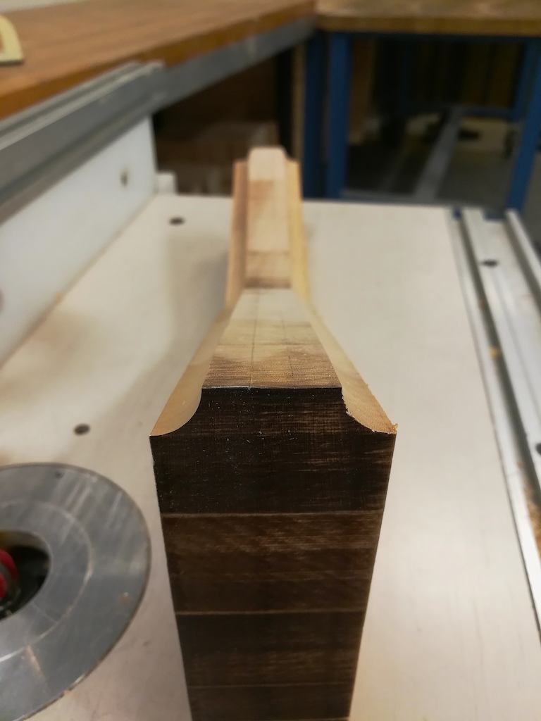
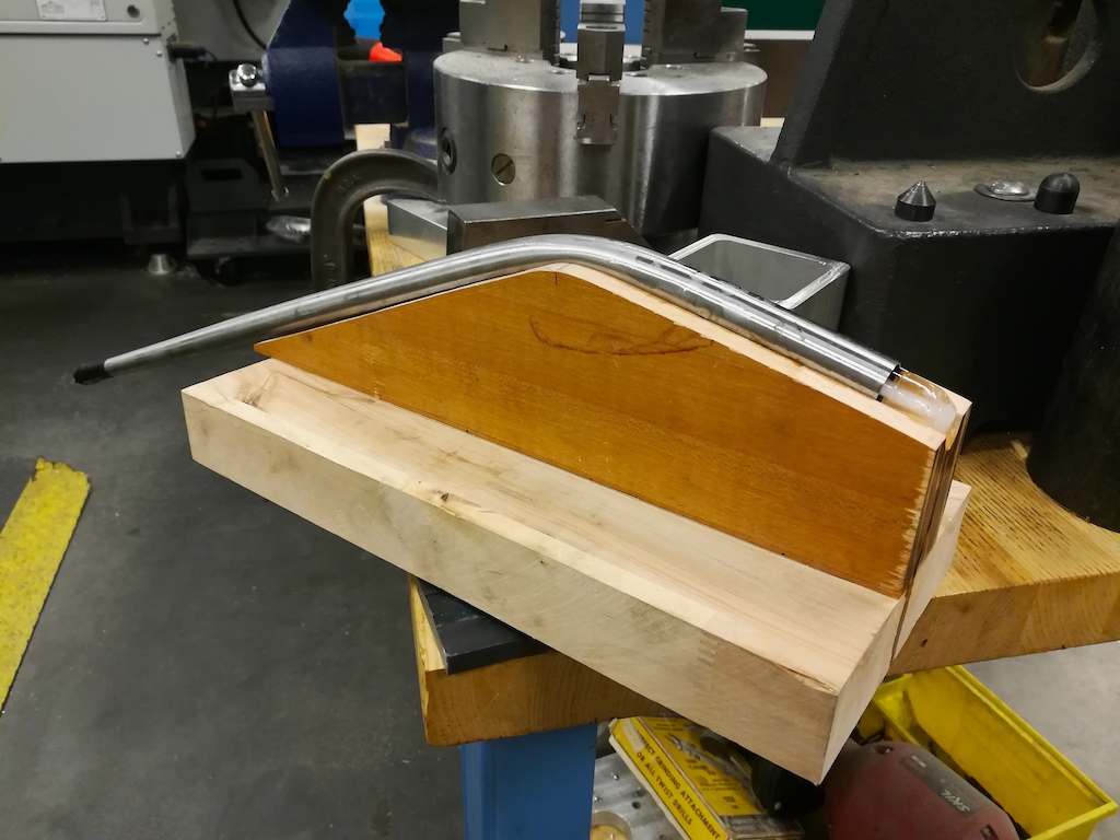
Bending chainstays proved to be a challenge. On top of 4130 not being a malleable material, the wall thickness was so thin that it proved much easier to kink the tubing than stretch it. Some stretch is needed since, during bending, the diameter of the curve on the outside of the bend becomes longer than the diameter of the curve on the inside.

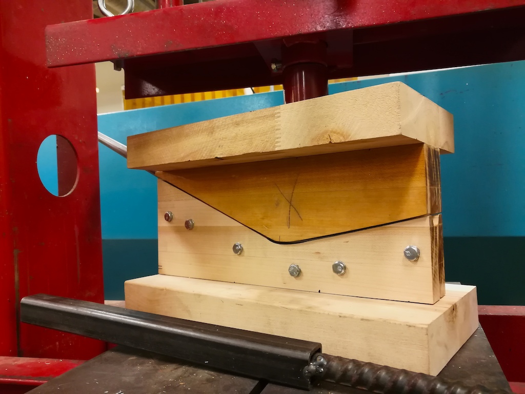
In order to counteract the kinking on the inside diameter of the tube, force needed to be applied against the inner radius. A traditional pipe bender could not prevent the tube from collapsing, even with sand packed inside the stays for additional support. I build a custom die for the bend on a router table, and the tubes were filled with water. After freezing the tubes for multiple days, I compressed the die in a hydraulic press and had great results. This needs to be done quickly, since the heat from deforming the metal melts the ice almost immediately.

Build - Part 4: Welding
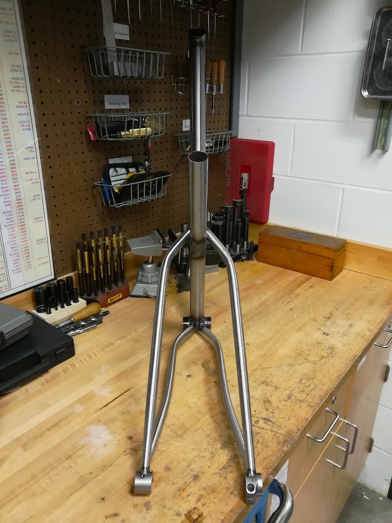
Once all the prep work was done, it was time to weld. Since the bottom bracket is essentially the origin of the bike, I started the welding process at the joint between the bottom bracket and the seat tube. Everything was built off of this point. From there I positioned my head tube in the correct location. In order to orient the head tube, I used string that was marked at specific lengths (for example reach), and a rotary protractor to measure angles. Once these three components were ready, I positioned the top and down tube and the final last minute tube fitment adjustments were made. From there, it was off to the welder.
Like I’ve mentioned before, I made sure to tack the entire front triangle together at once, alternating sides in between tacks. That way, I minimized any chance of the frame deforming when it cooled. Once it was all tacked together, I removed it from the jig so it was easier to handle, and finished the beads with as little stops as possible. Again, I worked on both sides of the frame evenly to minimize chances of it pulling out of alignment.

After the front triangle was finished, it was time to move on to the rear stays. Dropouts are often one of the most difficult parts of a frame build (the difference in material thickness is huge, and perfect installation is vital for many reasons). Left to right spacing must be exact in order to have an accurate chain line, and the dropout angle needs to be precise for quality shifting. This is one location where welding slowly and methodically and spending extra time to ensure proper jig alignment was critical.


Build - Final Touches
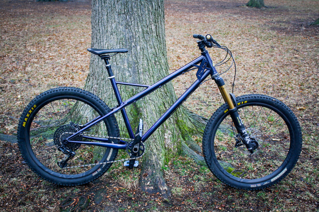
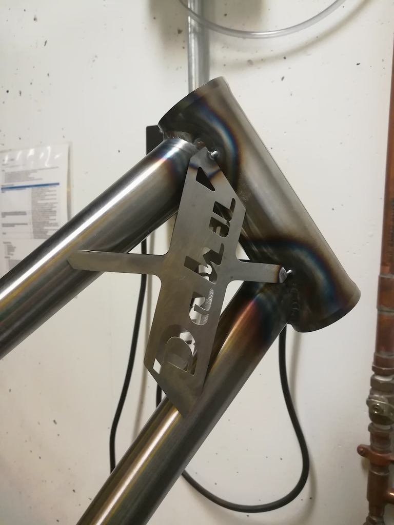
I named this bike Dahu, after a folkloric animal in Switzerland. The story is that there was a mountain goat like animal that had shorter legs on one side of its body, allowing it to only circle the mountains in one direction, and not allowing it to walk on flat ground. In other words, all it would do was keep lapping a mountain its entire life, good inspiration for a long day of riding.
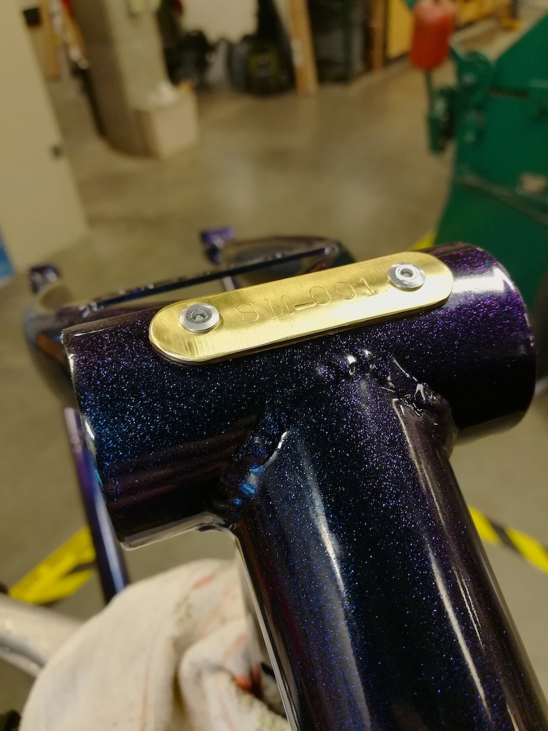
I wanted to include the name somewhere on the bike, and the gusset plate for the head tube seemed like the ideal location. I created a design and had the pieces cut on the water jet. Although not the strongest gusset design possible, it has become one of my favorite features.
To help stiffen up the rear end, I decided to include some braces for both the chainstays as well as seat stays. The seatstay brace once again utilized the Dahu name as well as the Dents du Midi (a mountain ridge in Switzerland). On the other brace, I drew up a Dahu and Swiss Cross.
All bikes have a serial number and so I decided to do mine with a punch and piece of brass that I found in the shop.
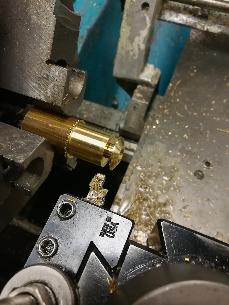
I also needed some bar ends, and thought that I could do something a little special. After turning down some brass bar stock, I had a set that I was excited to put on.
Finally, the all-important head badge. The most famous mountain in Switzerland, the Matterhorn, was formed with a metal shear. Using punches, I added the ridges into the sides of the mountain and the name underneath.

Assembly
Before the entire bike could be assembled, both the seat tube as well as the Paragon Head Tube needed to be reamed to the correct diameter. These parts are purposefully made slightly small, since they will deform very slightly during welding. Once reamed, everything can be installed smoothly with very precise tolerances.


Build - Part 6: Paint
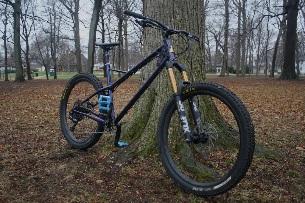
This is the one part that I didn’t do myself. I had the frame powder coated by a local shop, and what a show does the color put on! It’s called “Crazy Chameleon CC01” from Emerald Coatings. Link below.
Originally I planned to keep this build low cost, but in the process of searching for parts I found a complete Remedy for sale which became my sacrificial lamb. A friend also provided me with the wheels to top it off, a set of carbon Roval Traverse. Thanks, Kyler! Full component spec list below.
Although it’s not perfect, this experience has become one of my proudest accomplishments. University programs may find it difficult to support this type of program since it has no measurable academic value, at least not in the traditional sense, but I can safely say I learned just as much with this project as any one of my peers conducting research. Not only did I build a bike, but I worked through countless problem-solving opportunities. I learned dozens of new skills, worked with faculty throughout the university, and managed a project completely dependent on my own commitment. Thanks for reading, and to all those who helped me along the way.
Want To Build One Yourself? Here Are Some Tips:
- Clean the tubing. They need to be absolutely free of any dirt, dust, or packaging oils. All of this could affect the welds, and result in porosity or spattering.
- Always triple check fitment and angles. Make sure everything is exactly how it needs to be the first time.
- Clean the tip on your welder regularly. Tig is really the only way to go, and the Tungsten tip provides the best weld when it is sharp and clean.
- PRACTICE, PRACTICE, PRACTICE. There is only one chance to get this right. Chromoly is already not a very easy material to weld. Add on top the fractional wall thickness, and an extra second or a few too many amps could shoot a hole through your frame. Order extra tubes of all different types, and make sure you are 100% confident before diving in.
- Spend time preheating the thickest material with your welder before attempting to tack it in place. If this isn’t done, the tack will either only stick to the thin material, or will only glue onto the thick dropouts rather than welding into them.
- Find the most comfortable position prior to firing up the welder. Angles are very tight near the dropouts.
- Practice all your welding paths dry so that it’s not possible to get caught off guard.


Components:
Derrailleur:
Sram GX Eagle
Fork:
Fox 36 Factory 27.5 - 160mm, 15 x110mm
Cranks:
Truvativ Descendant
Brakes:
Sram Guide R
Headset:
Nukeproof EX44-40 - B5
Nukeproof ZS44-28.6 - T2
Pedals:
Deity Compound V2
Wheels:
Roval Traverse Carbon 27.5”
Tires:
Maxxis Aggressor 27.5”
Paint:
Crazy Chameleon CC01
Emerald Coatings
Materials:
Top Tube:
Down Tube:
Seat Tube:
Chainstays:
Seat Stays:
Bottom Bracket Shell:
Head Tube:
Dropouts:
Derraileur Hanger:
Cable Guides:
Huge Thanks to:
Craig Severson:
Allowing me free reign in your lab and being a great mentor
Josh DeLarm:
Teaching me the welding skills to make this possible
Kyler Steele:
Sweet wheels man!
Steve Salter:
Motivating me to finish this write up with your article “How I Built My Own Frame at Home”
Pheonix’s Powder Coating
Bike World Ames
Author Info:
Must Read This Week
How to Watch the 2024 Mountain Bike World Cup [Update: Staylive Offering Access in New Zealand, South Africa & More]
60119 views
60119 views
[UPDATED] Final Elite XC Results & Overall Standings from the Mairiporã XC World Cup 2024
41099 views
41099 views
Sign Up for the Pinkbike Newsletter - All the Biggest, Most Interesting Stories in your Inbox
PB Newsletter Signup
Few things to address here. Clearly I am no professional frame builder, and I had to really learn as I went. Therefore some welds are nicer than others. So much respect to all the guys (and gals!) that lay perfect dimes on this type of tubing every day! A whole new amount of appreciation for them.
The bike rides great! I took a week long trip with my brother as soon as I finished the bike, starting in Portland and road tripping down to Santa Cruz. Started off with riding Sandy Ridge, then the Mckenzie River Trail, and finishing on a bunch of shorter stuff in Santa Cruz. I don't really have any pictures of this since I was more focussed on riding, but it was a great time. I will say there are obviously some things it's better at than others. Super stable on down hills. Pump track was definitely a no go with the wheel base. Thankfully we brought a P2 as well!
I did have one breakdown on the trip, where I stripped a derailleur hanger. Paragon let me walk in and pick a few up in SF and we were good to go! Frame itself has held up well.
Feel free to send me any questions, I didn't really get into how I got to work on this project in college. I'll answer what I can!
Thank you for the write up. You did a great job!!!
Projects like this bring academia together with the real world. It's not obvious to the outsider how much time goes into even the smallest details like designing and building fixtures & jigs, or just how clean those thin tubes really need to be! I think going through the entire process yourself is super valuable, and you will be a much better engineer because of it!
The FEA stress plot seems quite unrealistic, especially the constraints. I hope this wasn't part of your academic project ;-) If I had been your tutor, I'd have grilled you for that. I worked in FEA for the last couple of years (instead of practicing my welding, haha)
I would have probably modeled bearing races and connected them via some sort of contact formulation to the headtube, and also modeled a "dummy fork" from a 1D element to account for the elasticity of the shaft.
The frame tubes themselves I would have modeled with a 2D mesh and the connections between them as fixed contacts. That would lead to a more realistic strain and stress distribution in the simulation
I'd like to see a proper FEA with and without the gussets.
Apart from that it's an awesome job.
This was added last minute as just a visual queue.
But again, awesome bike, be proud of yourself!
Thanks!
Personally, unless welding was a primary objective, I would have left that part to the experts. It would leave a smidge of doubt as to the true durability if the welds aren't proper.
I tried to do this in grad school (materials major) but with a carbon frame. I was shot down due to costs, lol. Pretty sweet though.
Welcome to the builder’s sect. Also, your story is delightibly written, well done.
Happy trails.
UncaJohn
Such a nice project!
Have you done heat treatment after the welding?
Thanks
Chris
So what do you want to do as an engineer?
Cool build