Introducing 'Behind the Numbers' - A New Suspension Analysis Series

Geeking out is damn good fun. But more than that, we can start to objectively analyse what’s going on with our bikes and form a connection between numbers and ride feelings and vice versa.
Feelings can only tell part of a story, and by the same token, numbers can only tell a different part. It’s in the combination of the two where we attain all the information and can start to understand the whole of what’s going on.
A bike is a myriad of parts that the information at ground level has to pass through to get to the rider. Behind the Numbers is a new series that takes a deeper look at the suspension link of the chain. And hopefully with the information we can start to understand this myriad of parts a little better.
The jungle of bold marketing claims and jargon is dense and tough to wade through. Biking is all about fun, and if we can get the tools to pick the right bike for our individual needs, we can extract the most amount of fun possible out of every ride.
Background
But who is conducting this scientific pick-apart of the bikes out there? Perhaps some history will help instill a touch of confidence while you read each analysis.
Since being knee high to a grasshopper, I’ve always found riding in and amongst the trees exponentially more fun than anything else. From then on, I’ve taken any excuse to get out on two wheels and away from everything. Days out digging with friends, to road trips riding in different countries, all brilliant excuses.
Undertaking a motorsports biased degree wasn’t a deterrent from bikes, and free reign over one of the most important projects of the degree said only one thing to me, so I designed a DH frame. I gained a mechanical engineering degree and set about trying to get a foot in the industry.

Dan Roberts // Technical Contributor
Age: 32
Location: Champéry, Switzerland
Industry affiliations / sponsors: Garage Bike Project, former engineer at Scott Sports
Instagram: @le_crusher
Age: 32
Location: Champéry, Switzerland
Industry affiliations / sponsors: Garage Bike Project, former engineer at Scott Sports
Instagram: @le_crusher
After quite a while badgering everyone in the industry with an email address (sorry about that!) I eventually, and what still seems by pure luck, landed a job working for SCOTT in Switzerland as a bike engineer.
When I started there, I was wide eyed and in a new land full of breathtaking mountains, excessive amounts of cheese and some of the most passionate and fun-loving people that one could hope to share adventures with. Those adventures ensued, be it in learning the right mixture needed to bake some of the most smile-inducing bikes that I’ve ever ridden, or off up a mountain side, with no more than a half-eaten cereal bar and sheer hope to get you to the tiny hütte on the horizon for the night.
We developed all manner of bikes and parts covering hardtails, full suspension, aluminum, carbon, stems, chain guides and even stuff that never saw the light of day. The variety of skills and experience on offer to learn was vast and wealthy. Three highlights include the Scale XC hardtail, the Voltage FR freeride bike and the Voltage dirt jump hardtail.
All things, sadly, come to an end. And with a lump in my throat I left SCOTT in 2017 to set out ticking off the riding spots on a list that adorned my fridge door. After 14 months, 12 countries, god knows how many kilometres and many more sets of brake pads than I am proud to admit, I had only one place that I wanted to return to — Switzerland.
I now call Champéry home, and run a small engineering consultancy to the bike industry called Garage Bike Project.
For me there was no other choice in my head than Champéry. Besides the riding that is on the doorstep and in the adjacent valleys, the crew of like-minded passionate pinners and the ability to scare yourself and have your socks blown off by the scenery on every ride, the opportunity to fluidly mix work and riding is the cocktail that I discovered to extract my best and most efficient work, while having a blast doing it.
Definitions
Before we delve into analysing the plethora of bikes available, we need to explain a few key terms that describe what’s going on.
Instant Center
This is the point that the rear axle is rotating around. On something like a single pivot bike, it's easy to see as the fixed main pivot on the main frame. On more complex, multi-link bikes this point can be out in space and not a physical part of the bike. As the suspension compresses and links move around, so does the instant center. This instant center is used to help calculate the leverage ratio, anti-squat and anti-rise.

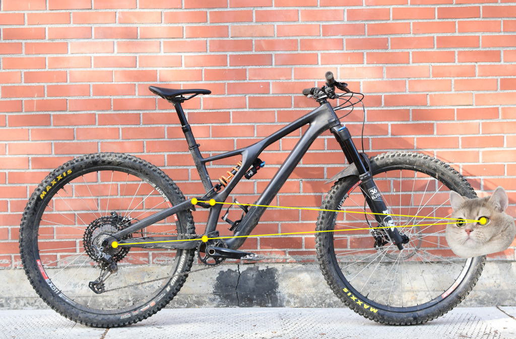
The Orange's instant center is the main pivot and a physical point. Whereas the Specialized's instant center is a point out in space dictated by the links.
Leverage Ratio
This the ratio between how much the shock moves versus how much the rear wheel moves. Most of the time it’s always looking at moving the shock 1mm (or whatever unit you would like, seeing as it’s just a ratio) and seeing how much rear wheel travel is produced via the linkage system.
1:1 would mean that the shock and rear wheel move at the same rate. 2:1 means that for every 1mm the shock moves the rear wheel moves 2mm. 3:1, the rear wheel moves 3 times the shock and so on and so forth. The higher the number, the higher the leverage ratio.
The leverage ratio can also tell us how much force the suspension system transmits to the shock from the rear wheel, and how fast or slow the shock will move.
A high leverage ratio will transmit more force to the shock, this is why you need bigger springs or more air for higher ratio bikes. A low leverage bike will transmit less force to the shock, requiring less spring force to push back.
The inverse, however, can be said of the shock speeds. At high leverage ratios the shock will be getting compressed slowly, and as damping is dependent on the shock speed, it will generate less damping force. A low ratio will be compressing the shock faster (it’s getting closer to 1:1) and will generate more damping force.
As links rotate and rear triangles move, the leverage ratio does too, and as we plot the leverage ratio for every point along the travel of the bike, we get the leverage ratio curve.

A linear, progressive and regressive leverage curve example.
Linear
Linear describes a leverage ratio curve that doesn’t change much throughout travel, i.e. a horizontal line.
Progressive
Progressive describes a leverage ratio curve that goes from a high ratio to a low ratio, so on the graph, it goes down.
Regressive
Regressive is the opposite of progressive and has a leverage ratio curve that goes from a low ratio to a high ratio.
Leverage Ratio Percentage Change
When we look at the difference in leverage ratio between the start and end of travel, we calculate the progression of the leverage ratio. Usually it’s described as a percentage. If a leverage ratio drops from 3:1 to 2:1 it has a change of 1, so we can say it’s got a progression of 33.3% (a third of the starting leverage ratio).
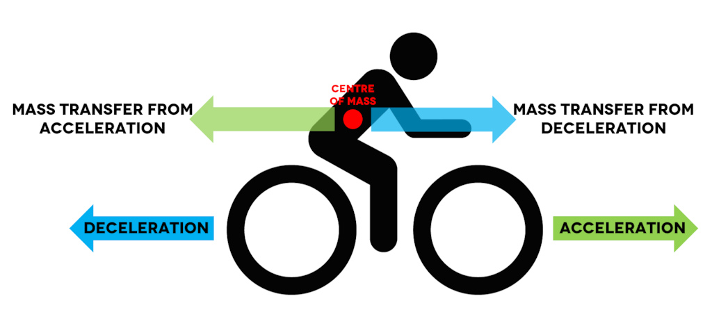
Mass transfer due to acceleration and deceleration.
Mass Transfer
When you slam on the anchors or mash the pedals your mass will move around. Physics is quite lazy, and so a mass always wants to remain where it is, be it still and not moving or just trundling along at a constant speed. If you start pedalling from a standstill, or brake while you’re moving forwards, your mass will want to stay right where it was while you’re actually starting, or stopping, moving. This lag causes our mass to transfer either forwards or backwards, and how our suspension system deals with this transfer can be described in two ways.
Anti-Squat
This is how the suspension system will deal with acceleration and the mass transferring backwards.
Imagine a big solid bar of steel propping you up, right at your center of mass; if you accelerate, you’re not going to compress this solid bar. The amount of force that the bar, or suspension system, pushes back with is exactly the same amount of force that your mass is falling backwards with. In other words, it’s 100%.
0% would mean that the suspension system doesn’t push back at all, and your mass transfer squats the bike into its travel.
200% would combat all the mass transfer forces and then still have the same amount again to push back with and so would make your mass move forwards.
Below zero figures mean that the suspension system is going the other way, and actually compressing itself further into travel while the mass transfer squats the bike too.
As you go further into your travel, the rear axle and BB get further apart from each other and stretch the chain. If you hold your feet where they are on the pedals, it needs a force to combat this chain stretch.
Anti-squat, however, is not the “chain force”. This seems to be getting used a lot amongst the industry at the moment, and it’s simply not true.
A suspension system will have a certain amount of anti-squat without the chain, and depending on what gear you’re in and how the chain lines up with the suspension system, it will either help, do nothing or have an adverse effect on the bike trying to combat the mass transfer.
Anti-Rise
When we talk about anti-rise, we talk about how the bike will react to mass transfer while braking, and so having the mass shift forwards. This pitching forwards effect would usually have the suspension system extending and having the bike rise out of its travel. Just like anti-squat it’s described as a percentage of how much the bike combats, or helps, the mass transfer.
100% would keep the mass at the same position while you brake by compressing the suspension, and 0% does nothing to combat the mass transfer and allowing it to move forwards with the braking.
Assumptions
Riding a bike is not a static process. That little quarter horsepower motor is moving violently all over the shop. To analyse things like anti-squat and anti-rise we have to make some assumptions to do the analysis in the first place, and then make it easier for comparisons between bikes. Otherwise it would be a mess.
These things are only analysed in a 2D nature, bike bolt upright and the mass transfer and reactions acting in the same plane. We assume a fixed center of mass height from the ground and we assume a fixed fork length. And for specifically anti-rise calculation we’re only braking with the rear brake.
For the center of mass, or COM, height we take 1150mm above the ground. For anti-squat calculations, where the chain comes into play, we use the extremes of the cassette and a cog in the middle. For example, on a SRAM Eagle cassette that would be a 50T, 24T and 10T. For bikes designed a bit more for pedalling up things, we take a 30T chainring for 29er bikes and a 32T chainring for 27.5. For bikes designed for going down, we take a 36T chainring and use the SRAM 7spd DH cassette as a reference.
These assumptions of course do not represent reality entirely, but as long as you know them then you can read the curves just fine and draw all the conclusions you need to understand what’s going on.
As previously mentioned, a bike is the sum of its parts. You can have the best suspension in the world, but if you mess the information path up with something as simple as tire pressure, then the outcome is going to be a negative feeling. We’re only focussing on one part of a bike here.
How It's Calculated
First, we need to measure the bikes, pinpointing each pivot’s location in space relative to some hard points on the bike, like the BB and rear axle. But we measure everything to know the link lengths, angles and layout of the bike.
These measurements get plugged into a 3D Computer Aided Design software package, where we create a 2D kinematic layout of the bike. There are only a certain number of dimensions that need to be inputted to have the sketch of the bike fully defined. But we measure more points on the bike to have more information to ensure the analysis is as accurate as possible.
From our software we can output all the data about the leverage ratio, anti-squat, anti-rise and axle path. But it’s not the prettiest and most intuitive to understand. So, we transfer the raw data over to a spreadsheet to form the graphs that we’ll have in the analyses.
The other tool used for the analyses is experience. I’m definitely not an expert, and am dubious of anyone who claims to be. We’re always learning. But what I’ve learnt so far - be it with development, engineering, riding or even just chin scratching with friends - provides the tools to speculate how the numbers will transfer into the real world.
 | Throughout the course of the Behind the Numbers series we’ll be looking at a whole range of bike categories and suspension systems. Hopefully you find it interesting and can take away some information that could help with understanding, buying or even just fuelling chin scratching conversations over a beer. |
Author Info:

Must Read This Week
[UPDATED] Final Elite XC Results & Overall Standings from the Mairiporã XC World Cup 2024
42385 views
42385 views
Sign Up for the Pinkbike Newsletter - All the Biggest, Most Interesting Stories in your Inbox
PB Newsletter Signup
Really enjoy reading the newest nerdy stuff, gives me the nergasm
One obvious question however since Scott Bikes have employed such clever & talented engineer's is what suspension system are they now favouring for their DH & Enduro bikes I wonder????
I'm looking forward to more of this series, and more science cat.
Speaking of, does lazer cat have a name, may I propose Dave Meowgle?
Your welcome
www.i-tracksuspension.com/suspensiontheory.html
Cheers,
Hugh McLeay
Because I am a Dork and not a Nerd, I tend to get flooded when words get too technical. I had to read each paragraph a couple of times to follow. Can I request more pictures to help explain the theories? I found I could understand leverage ratio and instant center right away (because of the pics), but the other stuff took me a few tries and I am still not sure I 100% got it.
Thank you,
Stupid Wannabe Nerd
Which topics in particular would you like more explanation of?
One obvious question since Scott Bikes have employed such clever & talented engineer's is what suspension system are they now favouring for their DH & Enduro bikes I wonder????
As I read the comments below I am seeing I am not the only one.... thankfully. I hate being the dumbest guy in the room and all my riding buddies work in aerospace
1. Mass transfer should be called load transfer - there is no actual transfer of mass. Semantics, but if we're trying to be accurate.
2. The terms rising rate and falling rate as explained here are basically flipped around. Rising rate refers to a rising spring rate as measured at the wheel, NOT an increasing leverage ratio. This is because the term originates from motion ratios (the inverse of leverage ratios), where as the motion ratio increases so does the effective spring/damping rate at the wheel. Progressive and rising rate mean the same thing.
3. Centre of curvature (CC) gives a better idea of axle path for pedaling purposes than IC, because the IC usually swings around a lot, and the CC defines the actual radius of curvature (ie rate of change of axle path) at any given moment where the IC does not. IC is the relevant consideration for braking purposes though.
By definition, the CC lies somewhere on the line from the Axle to IC. So it makes no difference to the AS calculation whether you use IC or CC (the first step in the AS calculation uses this line).
I agree that the CC is more stable than the IC, as it is effectively an 'average' of two consecutive IC points.
Sure, a user can get a better idea of the axle path from looking at the CC rather than the IC, but presumably they're already looking at it on some sort of software, which would already plot the axle path for them.
If just looking at a bike, i.e. not using some sort of software, you can approximate the IC location by eye, but it's pretty hard to approximate the CC without modelling it. So therefore, assuming you're using something like 'Linkage' it already tells you what the Axle path and AS curve looks like, without having to worry about the CC.
One thing the CC is good for though, is telling you how closely the AS curve resembles that of a single-pivot design. E.g. if the CC is relatively static, then the AS curve can be approximated by a single pivot configuration. Again though, this can also be observed just by looking at the AS curve (a single pivot AS curve is pretty close to linear, just with a slight curvature).
Interestingly, if you consider the CC to be defined as an 'average' of two consecutive IC points for the purpose of calculating AS, then there's also an equivalent virtual point for the purpose of calculating Anti-Rise (AR). It's basically the intersection of lines from the contact patch to the IC, for two consecutive suspension positions. You might call it the "Centre of curvature of the contact patch". I actually call it the "Centre of Braking" (for want of a better term), and you may have seen a checkbox 'CB' to show/hide it in the software on my YouTube vids.
In my next video on 4bar systems, I'll go into more detail about these virtual points (CC and CB), explain how they're defined, and then explain why they don't add much value haha. Yay for theoreticals!
And IMO the metric 'Leverage Ratio' should be banned! The world would be much simpler if we all just used 'Motion Ratio'.
Cheers,
Hugh.
29ers create more traction because the vertical motions of the axle are slower since the initial engagement of the tyre on a bump happens further forward of the axle due to the larger wheel diameter, meaning it essentially has more time to lift/lower the axle, resulting in smaller variations in contact patch load and lower frequency disturbances to the rest of the bike.
1. I was already hugely confused by this (see another thread that I started here) though I have to admit I still not entirely sold on the term load transfer. By load I still think of a downwards force which may hold on level ground, but when you want to look at the suspension performance when accelerating on a steep climb or change velocity on a decend I 'm not sure it will work as well. I just always thought the approach of KD makes one end of the EOM, FBD makes the other end and then you solve it was quite universal. Apparently not.
2. This one made me feel stupid. I always told people my Cannondale Prophet has a falling rate suspension design (for it to work nice with the progressive air spring) and then I read the article and thought I've been wrong all the time. But apparently some consider it the correct way around again.
Not meant to say I know better than others because I admit I don't know much about rear suspension and still haven't managed to ride one properly. Like, that I'm working with the suspension instead of fighting it. The geometry always seems to dislike my style of sudden weight shifts, stomps, pedal strokes and braking so that I just don't end up where I was aiming at. Hardtails are quite predictable! So I appreciate the articles and I'll try to get an idea of how the parameters relate to how it behaves. I ride my hardtail most of the time so no worries there but it would be cool if I could get the same kind of fun out of the fully. Thanks for the articles!
A linear spring rate will be constantly increasing in force as you move through the stroke and be a straight line moving steadily upwards left to right.
A linear leverage ratio curve will be flat, as the leverage ratio is constant (as shown in the graph)
A progressive spring rate will be accelerating upwards as you move left to right on the force curve, and will be a concave-up curve getting steeper and steeper.
A progressive leverage ratio curve will be decreasing as you move from left to right (as shown in the graph, but it doesn't have to be a straight line)
To throw more gas on the fire, what the rider feels on the trail is the WHEEL RATE and not the spring rate. This is the combination of the spring rate and the leverage ratio curve (spring rate at a certain point of the stroke divided by the leverage ratio at that same point in the stroke). The wheel rate is answering the question "how much force will it take to move the wheel another 1mm at this point in the stroke?"
In a rigid body, the mass is inherently fixed to the COM hence as the body accelerates in one direction, the mass accelerates the same amount in that very same direction. Sure I get that the rear wheel experiences an increased normal force from the ground and that on the front wheel is equally reduced, but it can't be explained using statics. Because it is a dynamic phenomenon.
In a simple (but for here sufficient) model we have a 2D rigid body with COM (center of mass) somewhere in the middle. Let's say the rear wheel is depicted left and the front wheel is on the right. Similar to the model shown in the article. In dynamics, you need two drawings.
One is the kinetic diagram (KD), showing the (angular) accelerations on the body. In this particular case, there is only a forwards acceleration of the COM. So that's one single arrow originating from that COM, going to the right in this KD. There is no angular acceleration.
The other diagram is the free body diagram (FBD) which shows the forces and moments on the body. In this case there is gravity pulling down at the COM. Both front and rear wheel experience a normal force from the ground, so that is upwards. The acceleration is caused by the drivetrain so the rear wheel also experiences a forwards push from the ground. So that is to the right in this drawing, parallel to the ground and at the bottom of that rear wheel.
Next step are the equations of motion (EOM). In 2D a rigid body has three degrees of freedom hence you're getting three equations. For this purpose I'll limit myself to the moment equation around the COM. The KD makes up the left hand side of the equation, the FBD does the right hand side. Because the acceleration goes through the COM, it doesn't have an arm hence the left hand side of the equation becomes zero. Because gravity also pulls through the COM it isn't contributing to the right hand side but the other three forces do. It is common to choose counter clockwise as positive direction so the contribution of the normal force on the rear wheel is negative, that of the drive force and the force on the front wheel is positive. Solve the equation and you're indeed going to find that the normal force on the rear wheel ends up being larger than it would have been in the static case (constant speed hence no acceleration) where the forwards driving force on that rear wheel wouldn't be there or if it would be canceled by an equal and opposite braking force from the front whee.
You're free to choose which point you take the EOM around and it won't get much more difficult as there is no angular acceleration anyway. A convenient alternative here would be to choose the contact patch under the rear wheel. In this case the acceleration multiplied by the mass and arm does end up in the left hand side (and negative). On the right hand side you now only find the normal force on the front wheel times arm (positive) and gravity times arm (negative). It is equally easy to solve and it will get you the same result.
I do see that people sometimes tend to do tricks on a dynamic situation (like considering the acceleration reversed) to then treat it like a static situation but I believe it is a dead end and will only lead to more confusion. It is just like the thing when people tell you that when they attach a mass to a rope and swing it around, that there is a force pulling that mass outwards. There just isn't. The rope applies a force inwards causing an acceleration (that is, change of direction) inwards.
Maybe this is just a Jobst Brandt type of argument but well, that would still make it properly bicycle related.
... So we won't listen to you.
You just got my upvote
I understand that this reduces the number of variables and allow comparisons between bikes, but what is the point of calculating suspension parameters of DH bike on flat ground model?
I mean can you just extrapolate how it will theoretically behave downhill or are these number then just pointless ?
However, this anti-squat number changes dramatically if you change the COM height! As weight-transfer due to acceration is proportional to the COM height, the required anti-squat effect to neutralize the effect of pedaling will be increase if you raise the COM.
So what is 100% anti-squat for a rider with a COM height of 1150mm, will be more than 100% anti-squat for a rider with a lower COM, or less than 100% anti-squat for a rider with a higher COM.
I think this is actually a big shortcoming in such analysis, beacuse a different rider will actually experience a different effective anti-squat. Generally speaking, taller riders will want higher anti-squat numbers than shorter riders.
My friend of 2.09 meters tall bough a Pole bike with a stated 80% anti-squat number (already pretty low!), but for his high COM the true anti-squat is certainly significantly lower, so he ends up with a bike that is actually showing a lot of pedaling influences...
100% AS being the best is open to discuss.
AS being even relevent for crank-imput related acceleration isn't obvious.
So one have to be very cautious when analysis Antisquat numbers.
I think the number has some use to compare bikes though, as a crude approximation of the pedalling efficiency. It's probably not a matter of what exactly is 100%, but more of being able to compare which bike is more or less supportive under pedaling. (provided the AS numbers are based on the same COM height! Otherwise the comparison goes out the window even between different AS numbers...)
At least the influence of COM height is quite 'simple', or at least predictable, so I brought it up because it can be useful for people who are deciding what bike would suit them based on stated anti-squat numbers. If you're a tall guy and you want pedaling efficiency, you should raise your 'sweet spot' anti-squat% because it's probably calculated based on a lower COM than yours.
As a 6’4” rider, the relationship between COM and anti squat is important to me. Also I believe that there are two sources of anti squat: chain tension and the location of the pivot relative to the line between the rear axle and your center of mass, and my intuition says that these two sources of anti squat will react differently to changing COM.
Is this accurate? And do the different sources of anti squat behave differently with respect to changing rider height?
If so I think it could be helpful to do anti squat analysis with two different COMs, to see how the relationship changes for taller/shorter riders. Maybe some bikes are pretty similar for riders of varying height, while other bikes require that you be close to a “sweet spot”.
Also this is probably way too much to ask, but maybe a quick mention of how different frame sizes are affected would be interesting. Do some manufacturers change these numbers based on frame size, or do they generally stay the same?
Knowing the basic physics of the frame is really helpful especially when incorporated with a "human" review.
Helps to cut through the marketing BS.
I have done several measurements in 3 riding positions of my self and come to average COG height 1100mm over the ground on 26" Banshee Rune V1.5.
My height/mass: 180cm/70kg
Wheel radius: 340mm
Bike wheelbase: 11335mm
COG height in
- pedalling position: 1200mm
- mild DH position (moved behing the saddle, arms fully stretched): 995mm
Use of some average safe value for COG makes comparing anti-squat and anti-rise graphs between the bikes very unprecise. I think, you should always measure actual COG on each tested bike.
I agree with you, some parameter(s) must be locked to be able to actually do some calculations (or estimates). What wheel size bike did you use to estimate the 1150mm COM height?
My mind is drawn to the Hightower LT, which was something of a plaster patch for SC while they worked out a fully developed bike, but in actual fact is recognised as being an amazing bike by those who've ridden it.
Take the article on the stumpjumper evo for example, the virtual pivot point will be close to the main chainstay pivot, just closer to the rear axle and down a bit, the instant centre is way out front, the whole application of instant centre to mountain bike suspension is 'theoretical' as it were, due to the fact there are other factors involved in pedalling efficiency, such as in-built mechanical inefficiency in the linkage itself to create a pedal platform, instant centre isn't the be all and end all of the equation.
My main point was that if the writer has not just made a typo and actually has a wrong understanding of instant centre, then the interpretation of all the data derived could be way off (being an engineer, even one employed in the field your writing about, unfortunately doesn't guarantee competence I hate to say, bridges still collapse and planes still crash).
The instant centre (of rotation) is a kinematic principle related to how bodies of a mechanism move relative to each other. It allows you to calculate the way forces are transmitted between bodies of a mechanism. It doesn't have anything to do with mass.
Here's a link explaining instant centres, and it makes no mention of mass or mass distribution.
en.wikipedia.org/wiki/Instant_centre_of_rotation
Based on your description of the Stumpy Evo in your post above, it sounds like you might be confusing it with the centre of curvature (CC) which is pretty close to the main chainstay pivot, while the instant centre (which you refer to as the virtual pivot point) is further out in front.
Or, perhaps you're thinking about the effect of the rotational inertia of each of the suspension members? This relates to the mass distribution within a body, and is certainly a valid thing to consider, but is pretty much impossible to quantify without have the CAD model of a bike, and its affect varies depending on the dynamic situation.
What you call the centre of curvature, would also be the pivot point, or in the instance of multi-link designs where the pivot point isn't fixed to a physical pivot location, it becomes a 'virtual pivot'
If you learnt that at university, maybe you should double check your notes.
Massless (theoretical) mechanisms have the same instant centres as those with mass.
Just google 'instant centre of rotation' and you'll literally find dozens of respectable resources confirming the definition.
Also google 'Kennedy's Theorem' or 'Arnold-Kennedy Theorem' to learn how to locate the instant centres of multi-link planar mechanisms.
This video might help too: youtu.be/JZus5ybcl0Y
Cheers,
Hugh.
Mass of the swingarm doesn't really matter here. The instant center this article is about is a point linked to the main frame. Whatever happens to the swingarm this point won't move.
The point you are talking about is linked to the swingarm itself and will change depending on swingarm movements. It won't tell us much about bike's feeling, it would be used to calculate movements of the swingarm after a specific hit.
If you or any readers want to dig deeper, I've got a video series going on YouTube which goes into great detail on some of these topics:
I've only done three episodes so far, but have a few more ready to drop soon.
Here's a link to Episode 1: youtu.be/T0GxNp98b7k
Cheers,
Hugh
For kids bikes a common problem is that you need to run the suspension pressures pretty low and modify to get less damping for both compression and rebound. One approach to this has been to give the kids bikes relatively high LR so that you can run the more typical pressures/springs that the shocks were designed for. It would be really cool to have a kids dual suspension bike tech out round up with plots like these for the kids bikes. As much as you say just let them ride, it really does seem to make a difference to get them setup right.
Maybe compare 20 inch and 24 inch dual squish bikes out there for kids including Spawn, Lil Shredder, Commencal, Meek Bros etc?
Maybe a second feature looking at dyno plots for "kids size" forces and see what shocks and forks offer the most options for tuning etc?
Dad's would appreciate it.
Coming to articles like this one is both helpful and confusing because in addition to trying to grasp how all of these terms affect one another, I then have to try and extrapolate that to a smaller rider who doesn’t have the mass to move the suspensions through their normal travel.
“Just let them ride” only works for so long. When they start hucking 20’+ jumps and 10’+ drops, it’s very important to have their bikes set up properly. Add that to the typical feedback you get from a kid: feels “good” (no matter what I do to it— from one extreme to another) and I’m even more confused.
So thank you for making this article series, but if you could include an extra few explanations as to how this would affect significantly shorter and lighter riders (52” types), it’d be greatly appreciated.
I know some, like Leo from Pole with their old bikes, and makers of other bikes with concentric BB pivots have argued that there is no energy loss possible with a BB pivot, and that while they are bobbing like hell, they are returning that energy. Leo even claimed at one point that using chain torque to resist bob from cyclical pedaling loads caused greater losses than just letting the bike bob with each pedal stroke, as the chain forces provided by the riders legs are having to support the suspension.
Without a power meter and completely matched bikes with 0% and 100% anti-squat, I can't make any objective statements, but I can say subjectively that all the 0% (or near 0%) anti-squat bikes I have ridden felt like you were pedaling through molasses with an elastic band for a chain. In other words, not good.
( in the case of a virtual pivot design i would recommend at least 5 reference points to describe the path that the pivot point passes along through out its stroke
Any article that states that the instant center is the pivot point for the axle path is so wrong that it is insulting and makes me sad
Are you saying we should be looking at a "Center of Curvature" type measure, like the Canfield Brothers suggest here: canfield-balance-formula.com/cbf-explained
When using the IC to give us an understanding of the axle path, all it's actually telling us is that at any instant, the trajectory of the axle is perpendicular to the Axle-IC line.
This video explains: youtu.be/JZus5ybcl0Y
Don't be sad. Physics is fun!
Cheers,
Hugh.
Simple ideas have been learned and forgotten just over the past thirty years - like, the Weagle suspension that factored in the granny chainring tension inside the lower pivot, serving to load the rear wheel under higher torque expected while climbing, but which has been entirely abandoned, with flimsy actual justification, over mammoth 1x cogsets that do magnify the chain effect on suspensions at low speed hill climbing. And so on, here we go again, proving why the latest is the greatest...
The only thing I‘m missing from the article are the pros and cons of each leverage curve. For example: Does a linear curve make for an active bike that can‘t handle big hits well?
Thou I have used this site a few times, linkagedesign.blogspot.com
Handy for some of the older bikes/frames
I've got a nerdy question for anyone who knows the answer:
Fox has digressive and linear compression and rebound tunes. Are the digressive tunes designed to be progressive to complement a bike that has a digressive suspension design? Or are the shocks tuned on their own to be digressive (to complement a bike with a progressive suspension design)?
Digressive damping in compression helps reducing suspension movements*, like when pedaling or braking. It also reduce suspension movement on bumps by a small amount. Extreme digressive damping in compression are "pedal plateform" for XC bikes or "lockout" features.
digressive damping in rebound is more complex to understand so I can't say I'm not wrong. But it will help with progressive bikes to have a more constant rebound thru the travel, it also slightly reduce suspension movement as in compression. But as rebound speeds are like 6x less than compression speeds, you can't have as much digressive rebound.
*reducing suspension movement doesn't always reduce chassis movement so it's not always something you want.
Here's what triggered that question.
I have a 2016 Niner RKT. Stock shock (2016 Fox DPS, Linear Medium Compression, Linear Medium Rebound, SV air can).
Shock is off being serviced, and in the meantime, I have a 2019 Fox DPS, EVOL SV air can, Medium Digressive Compression, and Medium Digressive Rebound.
The digressive tuned shock rides like crap. I feel like I have way too much sag, but am not using enough suspension travel. (There are no air volume spacers in the shock). These characteristics make me wonder if "digressive" shock tuning from Fox is actually designed to be progressive to work with a frame / suspension system that is inherently digressive.
If the shock itself was digressive, I would have imaged the opposite - either having not enough sag and / or using too much travel.
The only other difference is the EVOL air can. I realize that you need to run higher pressures with an EVOL air can, but does that change the rest of the shocks characteristics? (Niner did switch over to an EVOL air can on their newer bikes - they say it's the best option for the bike, however, Fox doesn't make a non EVOL air can in that size anymore, so maybe they got pushed into it by Fox.)
Lots of musing. I'm looking forward to getting my original shock back from service, and hoping it puts the bike back where I expect it.
Big difference is evol can that makes for a more linear spring rate instead of a digressive one, at the top. bigger air volume needs more pressure for the same spring rate. So the beggining of the travel is more supple, so bigger sag. If you pushed mor air to compensate you end up with an higher overal spring rate.
Digressive damping uses less travel if the overal average damping is similar.
There is enough difference between these shock to makes substancial diferences in ride feeling. If you didn't tune your fork for the new shock, it can feel like crap.
Your bike can feel better if you set your fork, like more psi and one or two clicks less of low speed compression.
Manitou mara
Motion ride flow evo
EXT storia
Push
Mrp hazard
Cane Creek inline
Xfusion new one
Add whatever rs/fox that's in vogue
We constantly hear about the need for a bike to have a progressive suspension curve in order to work well with a coil shock. Can you help me understand that assumption? Specifically, to run a coil successfully, is it ideal to have a higher amount of progression, or is it more important that the end stroke leverage ratio just be as low as possible (say, approaching 1:1)?
In theory, you could have a very progressive bike that still has a very high ending stroke leverage ratio (4:1 moving to 2:1, for instance) or you can have fairly low progression while having a low ending stroke leverage ratio (1.1:1 moving to 1:1), so it isn't clear to me which factor is more important.
Thanks so much
If you take a high pivot idler bike as an example, it has minimal chain growth but still has good anti-squat values.
Pushing the main pivot up on these bikes has put it more in-line with the direction of the mass transfer, that idea of trying to compress a solid bar, and so it "mechanically" resists it without the chain doing anything.
Depending on where the chain is pointing into the suspension system (it changes with what gear your in, what chainring size, if you've got an idler or jack shaft) the chain force could help fight the mass transfer (by extending the suspension), it could do bugger all to the total equation, or it could help the mass transfer compress the suspension further.
Hopefully that helps?
Until now, that's how I thought it works.
Progression percentage is ((starting ratio - end ratio) / start ratio) x 100.
For example, if the starting ratio is 3:1 and the end ratio is 2:1, the it's ((3 - 2) / 3) x 100 = 33.33%.
Just be careful if there are regressive humps at the start and end of travel, as that will affect the progression amount.
( Don't forget to link the reference article )
Will there be more articles in the future other than the few ones already published?